How to visualize WRF-Fire output in VAPOR
Prerequistes
- A working installation of WRF-Fire, possibly on a remote supercomputer or a cluster.
- A visualization computer with a decent graphics card and drivers (hardware accelerated OpenGL required), 3 button mouse.
- Download and install VAPOR
- Read Getting started with VAPOR first.
- On a Mac, run the installation package, then add to your path /Applications/VAPOR.app/Contents/MacOS
- Do the exercises in the first few pages of the VAPOR quick start guide to learn the basics of the controls.
- VAPOR can be used remotely over a version of VNC with OpenGL support, to avoid transferring huge datasets to your visualization computer.
Directions
- Change in namelist.input the line with history_interval to the desired frame interval in seconds, for example history_interval_s=1. Make sure frames_per_outfile is large enough so that only one wrfout file is produced.
- Run WRF-Fire. The pictures below are from the "hill" ideal run in WRF-Fire.
- If the visualization computer is different from the computer where you run WRF-Fire, transfer the wrfout file to the visualization computer
- Convert the wrfout file for use with VAPOR: run from the command line
- wrfvdfcreate yourwrfoutfile yourwdffile.vdf
- wrf2vdf yourwdffile.vdf yourwrfoutfile
- Start VAPOR by clicking on its icon or vaporgui from the command line
- In the GUI, click "Data" on the top menu bar, then "load dataset in the current session", and navigate to the yourwdffile.vdf you have just created. In the black right panel, you should see an empty wireframe box from the top.
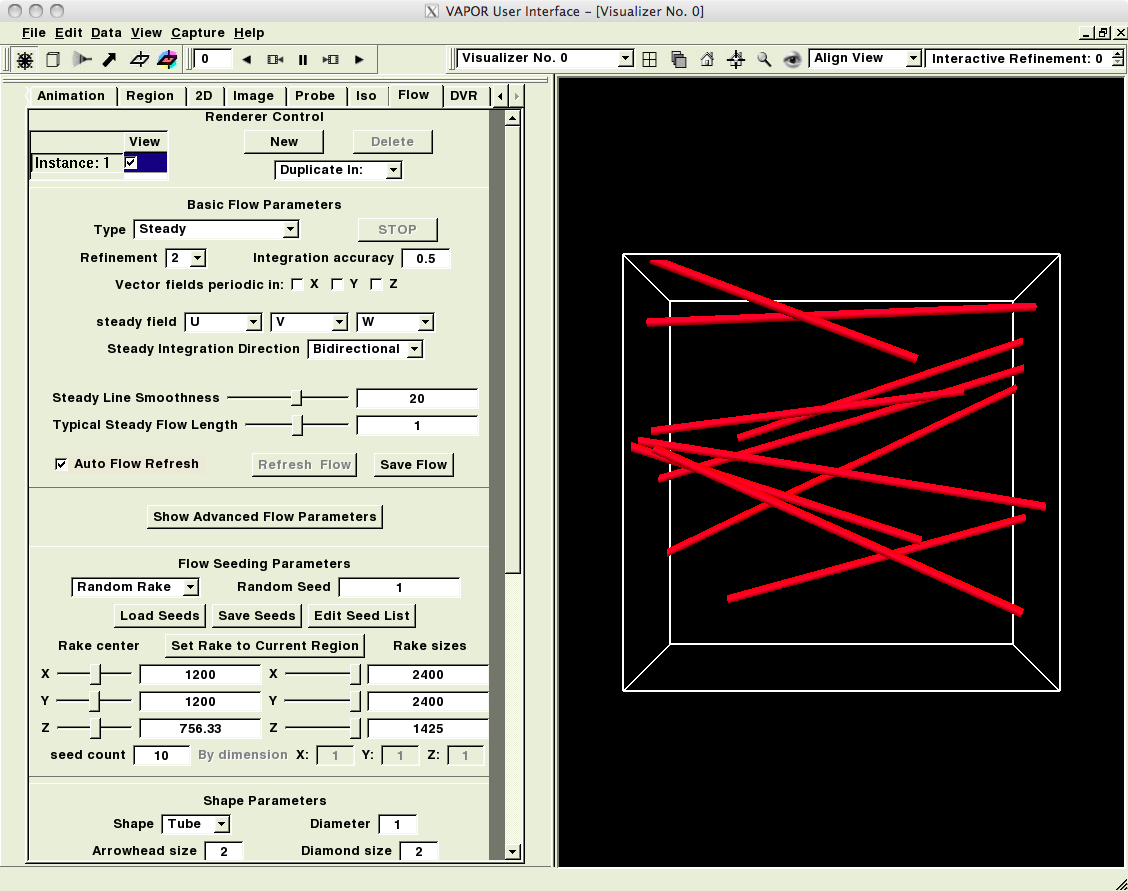
- Click the "Flow" tab, check the box "Instance 1", click "OK" on a warning about flow lines below zero. Select "Refinement" 2. You should see a picture like this (the starting points of the flow lines are picked randomly so they are different in every session):
- Click the "Animation" tab and move the "Frame position" slider to the middle (in the ideal "hill" example), or to a time when you know that the fire has already well developed. The flowlines should move a little.
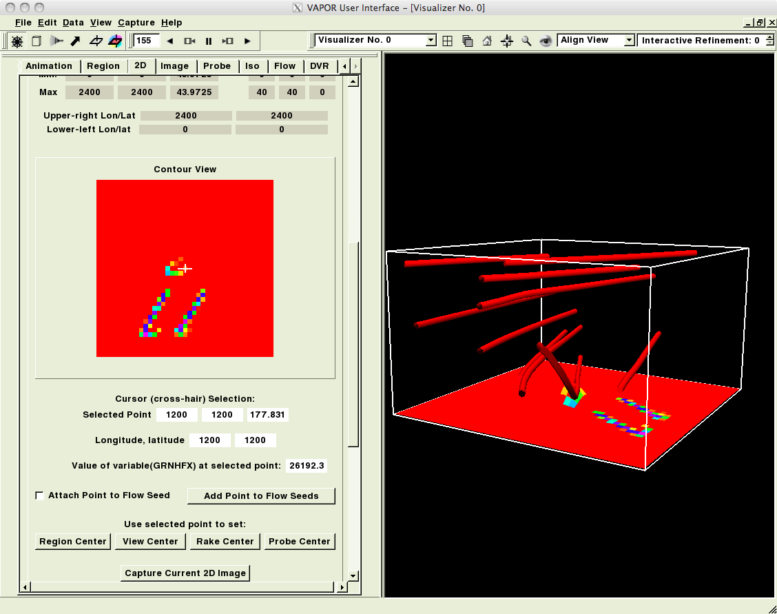
- Click the "2D" tab, check "Instance 1", select "Refinement" 2, and 2D variable GRNHFX, check "Apply color and opacity to terrain surface", and push the "Fit data" button at the bottom.
- Rotate the image with a mouse to see something like this:
- Click on the "Animation" tab, click on the rewind and play VCR controls, and watch the movie. If the movie is too slow, go back to the "Flow" tab and reduce the "Refinement" value.
- To capture the movie, use "Capture", "Begin image capture sequence in visualizer 0", select directory, then run the movie, when done "Capture" "End image capture sequence". You get the movie frames as jpg files.
- Use the DVR tab and other VAPOR features for a more advanced visualization as desired.
More advanced visualization
- Optional: If you plan to work with large files (over 2GB), recompile NetCDF in bash as
export WRFIO_NCD_LARGE_FILE_SUPPORT=1
and then run in your netcdf directory
./configure  --disable-netcdf4 --disable-dap  --enable-large-file-tests --prefix=the contents of your NETCDF variable
make
make install
make check
The last command will create, manipulate and delete some large files, so expect that it will take some time to finish (note the "--enable-large-file-tests" switch). If you do not have nco for command-line manipulation with large files, install it on a Mac simply as
sudo port install nco
and see its user's guide if you wish. It should not be necessary (I believe) to reinstall WRF-fire.
- If the wrfout file contains all WRF variables, which is way more than we need at this point, it is convenient to select only the desired variables: U,V,W for wind streamlines, GRNHFX for fire, QVAPOR for smoke and AVG_FUEL_FRAC for the burned area.
The selection of variables can be done in two ways:
- create new NetCDF file with this variables by ("-O" switch overrides the file and if some variable is not available, simply skip it)
ncks -v U,V,W,QVAPOR,GRNHFX,AVG_FUEL_FRAC,PH,PHB,Times wrfout -O file
wrfvdfcreate file file.vdf
wrf2vdf file.vdf file
The wrfvdfcreate command creates a vdf metafile with a description of the data for Vapor and wrf2vdf created a directory file_data with the actual data.
- the other option is to specify the variables in the wrfvdfcreate call, i.e., run
wrfvdfcreate -vars3d U:V:W:QVAPOR -vars2d GRNHFX:AVG_FUEL_FRAC  wrfout file.vdf
wrf2vdf file.vdf wrfout
This would create a directory wrfout_data with the same content as the directory file_data above.
- Start VAPOR by clicking on its icon or vaporgui from the command line.
- If you are provided a "Vapor saved session file" *.vss click "File" in the top menu bar and load this file by "Open session" dialogue. In either case, click "Data" in the top menu bar, then "load dataset in the current session", and navigate to the file.vdf (you might have just created). In the black right panel, you should see an empty wireframe box.
- To label the axes with coordinate values click "Edit" in the top main menu, then "Edit Visualizer Features" and check "Show X, Y, Z (R,G,B) Arrows". You can also add "Enable axis annotation", "Time annotation", etc. In case you do not have a terrain image and you will not be able to acquire one using the steps described below, you might check "Display Terrain Surface" and pick (a constant) "Color" you like. If you have an image, do not import it here, but use the "Image tab" discussed below.
- If you do not have an image of the terrain, but your wrfout file contains the geo-coordinates of the domain you can acquire the image from the internet. If you already have an image or you don't know the coordinates then skip this step. We will use Vapor's bash-shell script getWMSImage.sh for retrieving maps and imagery from a Web Mapping Server (WMS). The call of the script has a general form
getWMSImage.sh [options] minLon minLat maxLon maxLat
where we will use the following options to specify: map type -m landsat (the other option to consider is BMNG, but it seems to give worse quality images), the output file -o filename.tiff and the pixel resolution -r xres yres (the default is 1024x768). Assuming that minLon minLat maxLon maxLat are given as -95.03 29.3 -95.01 29.4, an example call of getWMSImage.sh can be
getWMSImage.sh -m landsat -o fireflux_terrain_geo.tiff -r 1180 1580 -95.03 29.3 -95.01 29.4
Such an image will be automatically geo-referenced, i.e. it will include the longitude/latitude information. If you have a tiff image which is not geo-referenced, e.g., an image obtained from the Google Earth screenshot, you can use tiff2geotiff to convert it to a geo-referenced terrain image as
tiff2geotiff -4 "+proj=longlat" -n "-95.03 29.3 -95.01 29.4" fireflux_terrain.tiff fireflux_terrain_geo.tiff
- If you have a tiff image of the terrain click on the "Image" tab. In VAPOR 1.5.0 you are allowed to use only tiff images without any compression. If your image is a tiff but not a geotiff (or you are not sure) uncheck "Georeference", then "Select Image File" and navigate to your file. Finally check "Apply image to terrain" and "Instance: 1". After the image is displayed you may also check "Crop to bounds" if needed.
- Click the "Animation" tab and move the "Frame position" slider to a time when you know that the fire has already well developed.
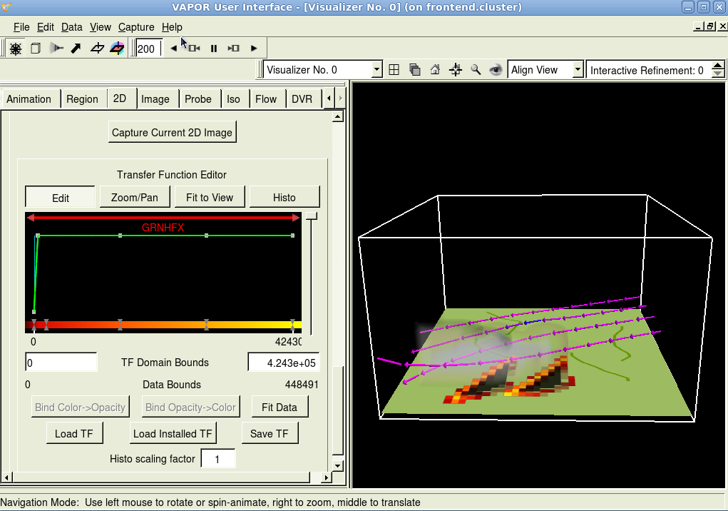
- Click the "2D" tab, select variable GRNHFX, check "Refinement" 2, and "Apply color and opacity to terrain surface", If you do not have *.vtf file, set at the bottom of the tab the colormap and opacity as, e.g., in the following picture (the opacity is sharply cut off near zeros values and set full elsewhere, so that the areas not on fire are fully transparent):
If there is a *.vtf file available for the colormap and opacity, click "Load TF" and navigate to the file. Finally, check "Instance: 1". You should see the fire area on the terrain. One might also check that the "Z-center" coordinate has a slightly higher value in the "2D" tab than in the "Image" tab, i.e., that the fire will be displayed 'on top of the terrain'.
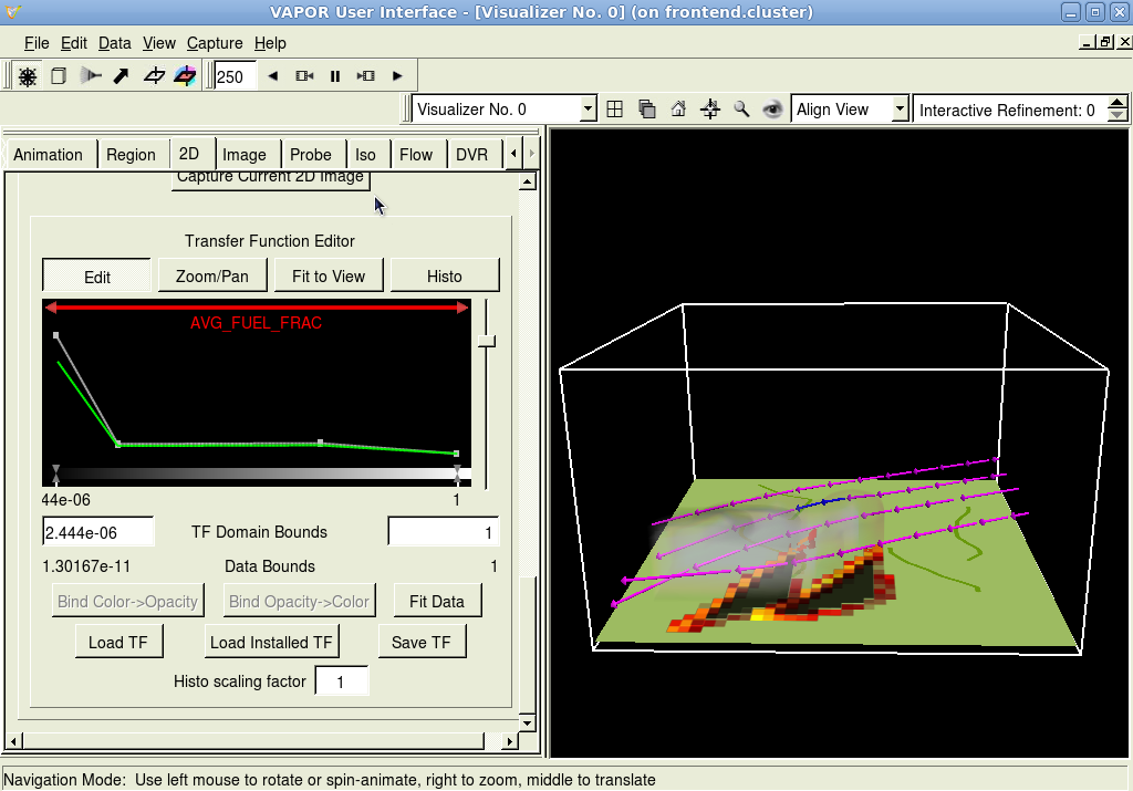
- On top of the "2D" tab under "Renderer Control" click "New" push "Instance: 2" and select the AVG_FUEL_FRAC variable, check "Refinement" 2, and "Apply color and opacity to terrain surface". Scroll down to "Transfer Function Editor", click "Load Installed TF" and select grayscale.vtf. The settings for opacity are illustrated by the picture below (the opacity is high and color is dark for regions with little fuel remaining):
One might also like to make sure that the z-coordinate for AVG_FUEL_FRAC is a bit below the GRNHFX z-coordinate and a bit above the z-coordinate for the terrain image. Note that the AVG_FUEL_FRAC variable might not be convenient if there are areas that do not contain any fuel a-priori.
- Click the "Flow" tab, make sure that the "steady field" variables are U, V, W and select "Refinement" 2. Scroll down to "Flow Seeding Parameters", select "Nonrandom Rake" and "seed count ... By dimension" to ,e.g., 3, 3, 1. In the "Shape parameters" area set "shape" to arrows, decrease "Diameter" to e.g., 0.5 and in "Color/Opacity mapping" area set "Color" to "Position along flow". Check the box "Instance: 1". If there is a warning about flow lines below zero click "OK", but follow the instructions: in "Edit" top menu select "Edit Visualizer Features" and in the "Variable values outside grid" uncheck for U,V and W the "Extend, down" box so that the "Below" appears in white with 0 value in the box. Hit "Apply" and "OK". One might also like to position the flow streamlines in the vertical direction. This can be done in two ways: either by sliding the "Rake center/sizes" slides in the "Flow Seeding Parameters" portion of the tab, or by clicking the "Region Select Mode" which is the second icon (the box) from the left under the top menu bar. This will display a box with handles in the visualizer window (see the image below) which can be resized by clicking and dragging with the right-button on the mouse. After the region is set, click the"Navigation Mode" icon (the rudder) which is the very left one under the top menu bar.
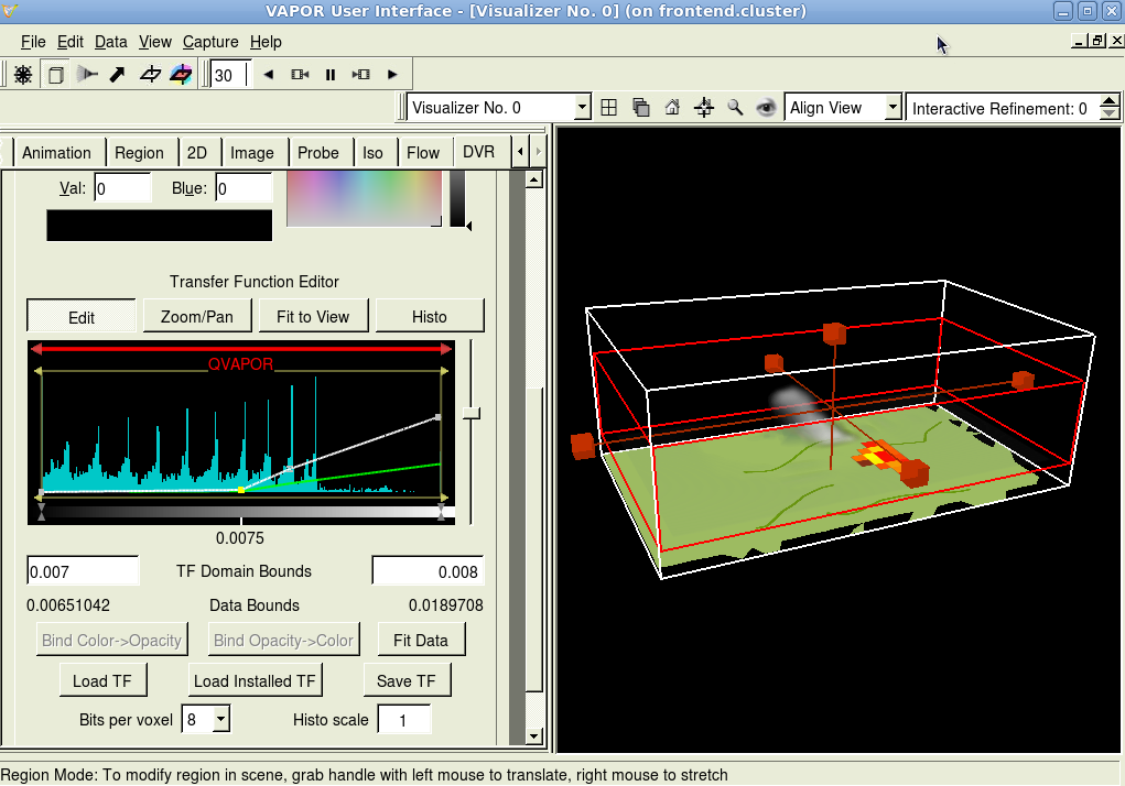
- Click on the DVR (Direct Volume Rendering) tab and select the QVAPOR variable, which is used to visualize the smoke. This is the tricky part which can be in my opinion hardly 'automated'. One might like to decrease the vertical size of the region in a way described above because there might be a significant amount of vapor present higher in the atmosphere. An example of setting for color and opacity are illustrated by the following picture:
Note that the displayed data correspond to the lower 1/3~1/4 (approximately) of the range of values and opacity increases slightly with the values. "Load Installed TF" as grayscale.vtf and ev. shuffle the color control points if you want the smoke to appear more dark. Also, it might be better to leave the "Refinement" 0 not only because DVR is computationally demanding but also it might provide (surprisingly) better appearance of the fire. Also if one is still looking for the best point of view and is moving the region, it is recommended to uncheck the "Instance: 1" for the moment until the final point of view on the region is found. If the ultimate goal is a video sequence it is better to watch the full sequence using the controls in the "Animation" tab before the final decision about the (color and opacity) settings in the DVR tab for the QVAPOR variable are made.
- To capture a single jpg image, click "Capture" in the top menu bar and "Capture a single image in visualizer 0" and follow the instructions.
- To capture a sequence of jpg images (to be post-processed into a video out of Vapor) click "Capture" in the top menu bar and "Begin image capture sequence in visualizer 0", select directory, then run the movie in the "Animation" tab or using the controls next to the top menu bar, when done click again "Capture" followed by "End image capture sequence". You get the movie frames as a sequence of jpg files. The sequence of images can be processed into an avi in Virtual Dub under windows or using
ffmpeg -f image2 -r 1 -i fireflux_small_%04d.jpg -r 25 -s 512x512 movie.avi
under linux/Mac. The first '-r 1' means the frame rate of the input, so 1 means each picture is displayed for 1 second, 10 means 1/10 of a second, and so on. Use this to adjust the speed of playback. The '-s 512x512' means the resolution of the output in pixels (width x height). While ffmpeg will let you put any numbers here, you should make sure that the width and height are both divisible by 16 otherwise some movie players will not be able to play it.
It looks for input images starting at fireflux_small_0001.jpg and continues until a file doesn't exist. This means if the output starts at 0000, then the first frame will not be in the movie. I don't believe there is a way to configure this aspect of ffmpeg.
This command will create the movie and compress it using a common video codec. It will you use the highest quality setting by default, which is overboard for this kind of movie. So if the files still end up larger than we want, we can always add a couple of more flags to limit the bitrate of the output.
- Use other VAPOR features for a more advanced visualization as desired.
Works with
- WRF-Fire May 26 2010 and hopefully later
- VAPOR 1.5.2 and hopefully later
- Tested on MacBook Pro 4GB OS X 10.6 GeForce 8600M GT 512MB
